Sometimes it is useful and/or necessary to add a cut/fill line to your grading plan that you are issuing to the contractor. It has been awhile since I've had to do this (before we changed to Civil 3D) so I had to re-teach myself how to do it. I'll will show you here how I approached this task.
Adding a Cut/Fill line is relatively simple if you know your way around Civil 3D. The cut/fill line is the zero elevation contour on your "Tin Volume" surface that you have created to get your earthwork numbers. To find this zero elevation contour, you are going to change your styles to reflect a "user-defined contour."
Consider the figure below: In my toolspace under the prospector tab, I have three surfaces that I've created; My existing ground surface (EG), my proposed grade surface (PG) and my tin volume surface (EW - for earthwork).
There are several ways to create new styles. I normally copy and existing style that I have and change it to display what I need it to. First, right click on your tin volume surface and go to surface properties.
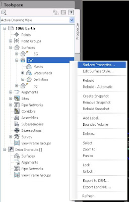
The surface properties dialog box should appear.
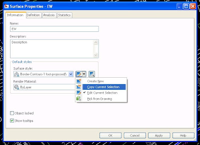
Press on the "down" arrow next to the surface style box. Here you can create new, copy current selection, edit current selection and pick from drawing. I clicked copy current selection.
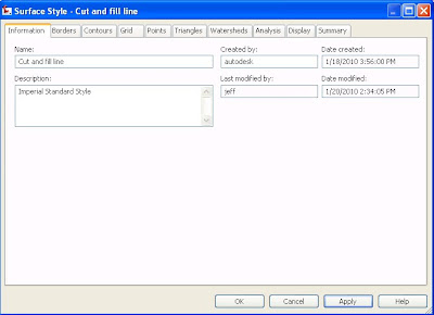
Under the "information" tab, change the name to "Cut and Fill Line."
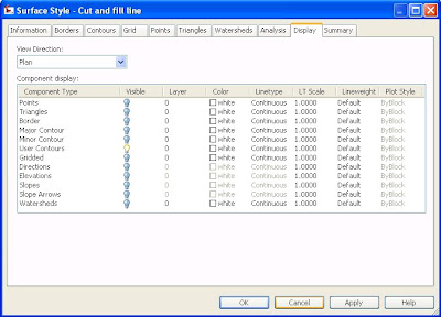
Next, click the "display" tab and turn off all the layers except for "user contours." Then click ok.
Go back to the surface properties dialog box and click the "analysis" tab. Here you need to check your min/max elevations.
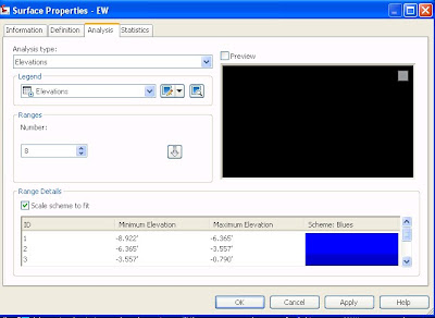
Mine were -6 and 12 so I'm going to go back and edit my cut and fill style.
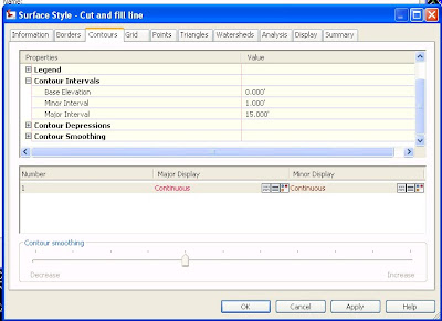
Go to the "contour" tab and change the major contour interval to a number higher that your max elevations. I changed mine to 15.
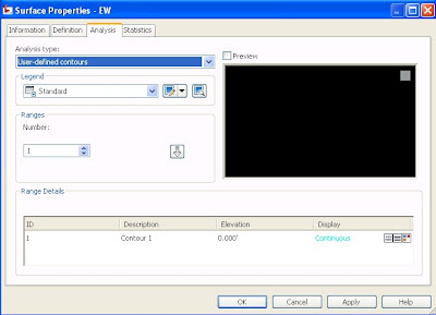
Back under the surface properties dialog box, click the "analysis" tab. Under "analysis type" change that to user-defined contours. Under "ranges" changed the number to one and hit the down arrow beside it. Under "range details" change the elevation to "0." Click okay. That should show you the zero elevation contour for your tin volume surface.
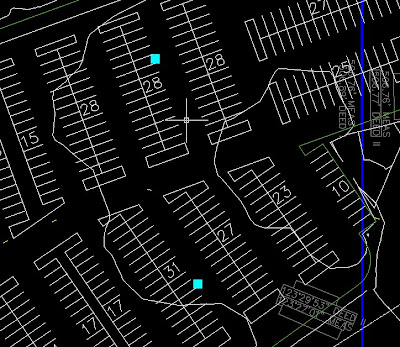
You should end up with something like the image below. The squiggly white line is my zero contour line. Of course you can go and edit your display of that line to make it look how you want (change the color, linetype, ect.) or there are probably ways to extract that line from the surface to a polyline. But if you are old school like me, you'll just trace over it. ;)
Til next time, Folks...
No comments:
Post a Comment